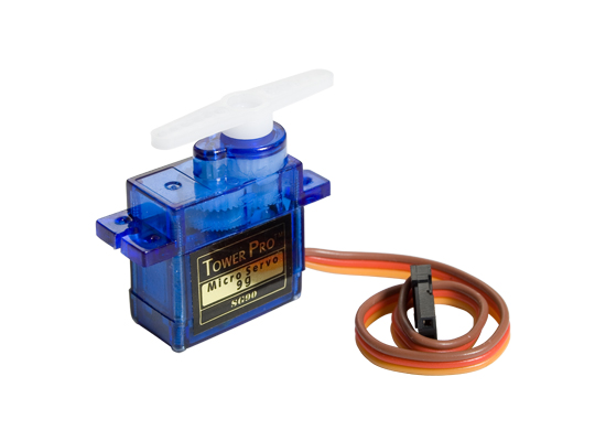
SERVO MOTOR INTERFACING WITH NODEMCU
In this project, we will learn how to control the position of a servo motor using NodeMCU based on ESP8266 microcontroller and Programming with Arduino IDE software. A servo motor is a rotary motor that allows you to control the motor in specific angular position, velocity, and acceleration. Servo motor works on PWM (pulse width modulation) principle and basically made up of DC motor which is controlled by a variable resistor and gears.
Synopsis

In this project, we will learn how to control the position of a servo motor using NodeMCU based on ESP8266 microcontroller and Programming with Arduino IDE software. A servo motor is a rotary motor that allows you to control the motor in specific angular position, velocity, and acceleration. Servo motor works on PWM (pulse width modulation) principle and basically made up of DC motor which is controlled by a variable resistor and gears.

Description


Servo Motor

There are some types of applications where the rotation of the motor is required at a specific angle for a given electric pulse to make this possible servo motor came into existence. Servo motor rotates as much as we require and stop and waits for the next signal to take further action. A typical servo motor consists of three parts -Power, control, and ground. There are different types of servo motors they are.

1.DC servo motor

DC servo motor is the same as DC motor but differs in construction, design, and operation. This type of motor is designed with long rotor length and have a small diameter. There are different types of Dc servo motors they are.

a. Series motors

b. Split series motor

c. Shunt control motor

d. Permanent magnet shunt motor

2.AC servo motor

Ac servo motors are AC motors in which encoders are used with controllers to provide closed-loop controllers and feedbacks. These motors are positioned at high accuracy. They are classified into two types

1. 2-phase servo motor

2. 3-phase servo motor

3.Brushless DC servo motor

They are commonly known as synchronous motors that have DC electricity with switching power supply. Hence provides AC current to drive each phase of the motor with a closed-loop controller.

4.Positional rotation servo motor

These are the most common types and important servo motors. The shaft output rotates about 180degress. It includes a physical stop gear mechanism to stop turning outside that limits to guard the rotation.

5.Continuous rotation servo motor

These are related to common positional rotation servo motor but can go in any direction. The range of position commands the servo motor to rotate a clockwise and anti-clockwise direction as preferred.

6.Linear servo motor
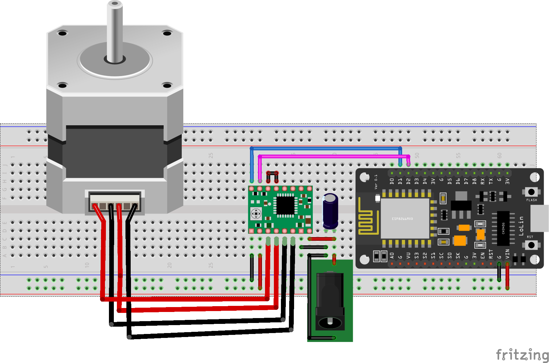
These motors are similar to positional rotation servo motor by extra gears that are used to alter the output to move backward and font.

NodeMCU

A NodeMCU is a development board with an inbuilt Wi-Fi module in it. It is a basic and cost-efficient board to carry out projects using the internet of things. The NodeMCU has an ESP8266 microcontroller unit in it. The operation of this microcontroller is controlled with the programs used in Arduino thus making it very easier to use and also to learn basic IoT projects. This board has an inbuilt 2.4GHz antenna to receive Wi-Fi functions. This board has a memory of 4mb to store the data acting as ROM and 64Kb of RAM. This board operates at 3.3 volts and it is mandatory to operate the board at this voltage and not more than that as increasing the input voltage in this board may damage few GPIO pins (general input-output pins).


Pin Configuration of NodeMCU

1. Vin: 3.3V can be provided at this pin as the supply to power on the board. This pin is used to power on the entire microcontroller.

2. GND: This pin is connected to the negative terminal of the battery.

3. RST: This pin resets the microcontroller and clears the memory.

4. EN: This pin is used to enable the operation of microcontroller.

5. 3V3: This pin provides 3V output and this can be used to power up some sensor units connected to the microcontroller.

6. SD1, CMD, SD0, CLK: These pins are used in SPI communication, that is it is used to transfer the signals between two microcontrollers, Rx and Tx modules with asynchronous transmission.

7. SD3, SD2: These pins can also function as asynchronous transmission or as GPIO pins.

8. RSV: These are two reserved pins used by the microcontroller and cannot be used in connecting any external circuits to it.

9. A0: This microcontroller only has one analog pin for Analog communication. This A0 pin is used in analog signal communication.

10. GPIO 1 – 16: This controller board has 16 input-output pins which be used as input or output pin based on the programming.

11. GP10 1, 3, 13, 15: This microcontroller has 2 UART communication pins, RX0, TX0 (GPIO 1 & GPIO 3) and RX1, TX1 (GPIO 13, GPIO15).

Schematic


Code

#include <Servo.h>
Servo myservo;
void setup() {
  myservo.attach(D1);  // ATTACH SERVEO TO D1 PIN
}

void loop() {
  int pos;

  for (pos = 0; pos <= 180; pos += 1) { // it goes from 0 degrees to 180 degrees
    // in steps of 1 degree
    myservo.write(pos);    
    delay(15);                    
  }
  for (pos = 180; pos >= 0; pos -= 1) { // it goes from 180 degrees to 0 degrees
    myservo.write(pos);     
    delay(15);                     
  }
}

Error message here!

Show Error message here!


Forgot your password?

Error message here!

Send OTP

Error message here!

Show Error message here!


Lost your password? Please enter your email address. You will receive a password you Need.

Send Error message here!


Back to log-in

Close